Overview Link to heading
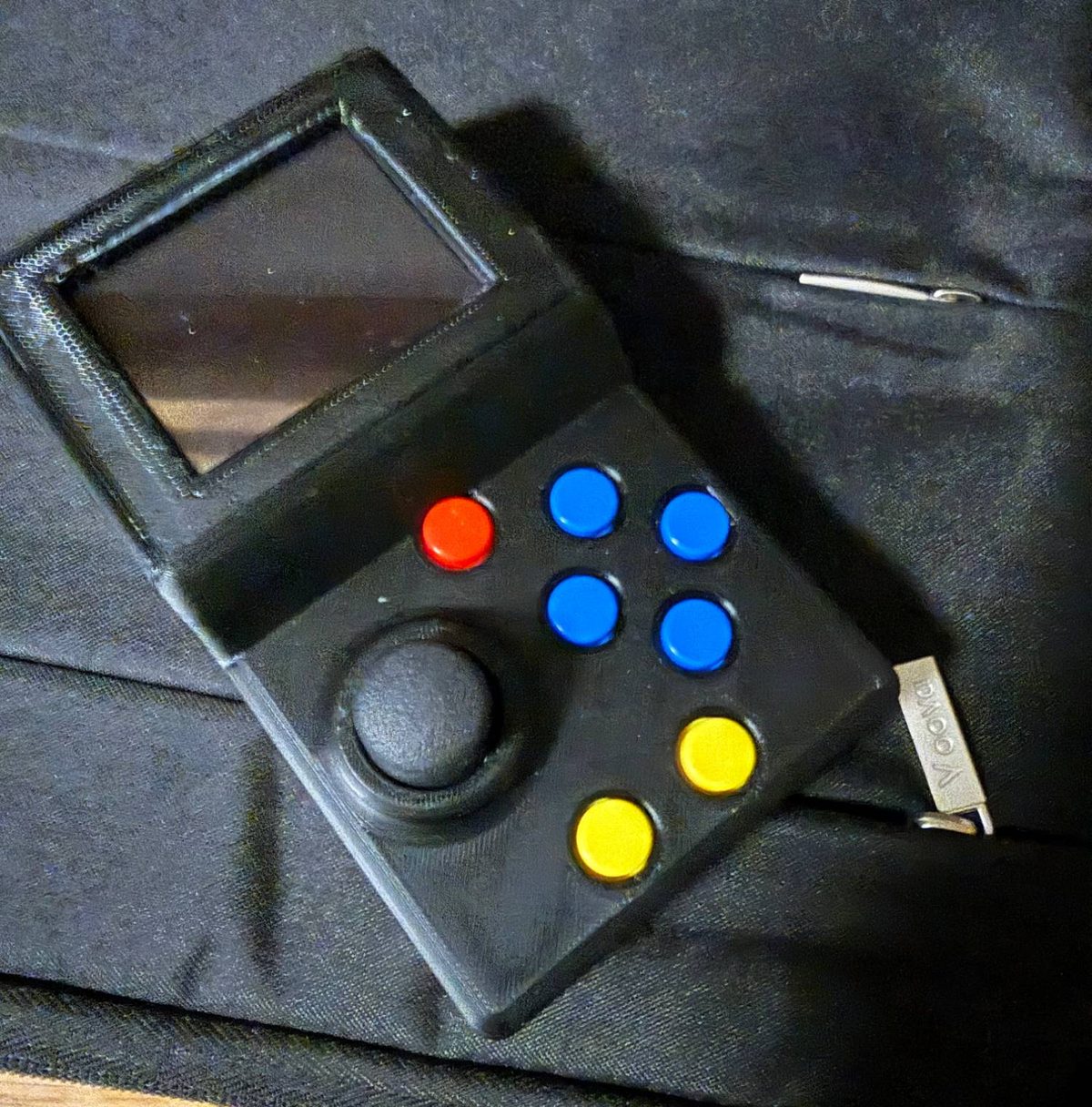
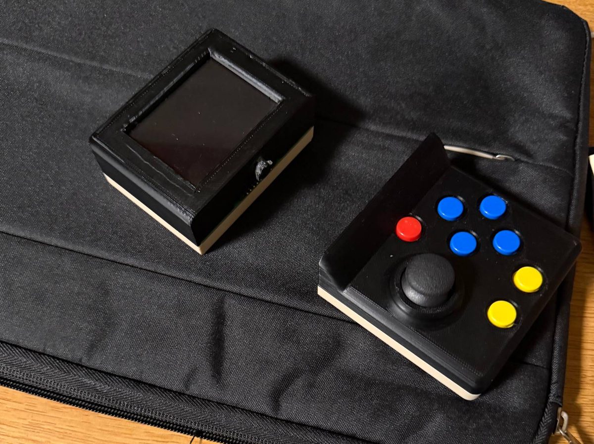
The goal of this project was to learn how to design and implement a modular system that a user could easily interact with. The base unit contains the Pimoroni Pico LiPo (Raspberry Pi Pico variant with battery charging) as well as the display, and different control modules twist lock onto the bottom, with a magnetic pogo pin connector providing the electrical connection. The first module I built is a retro gaming controller, with future plans for more modules.
How it works Link to heading
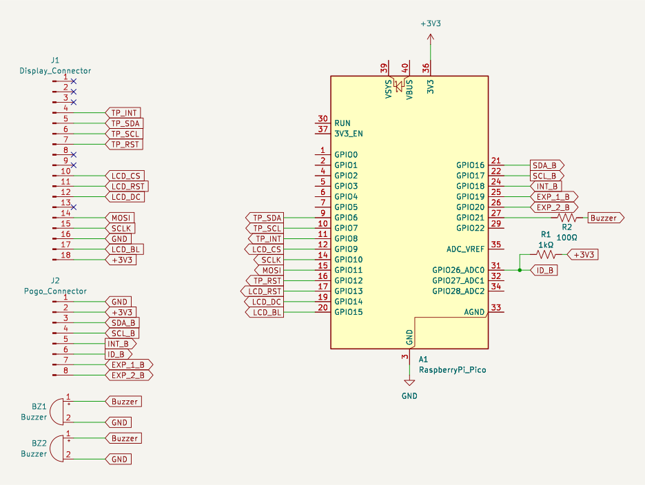
The base runs on a Pimoroni Pico LiPo with MicroPython. It drives an ST7789 display over SPI through an 18-pin FPC ribbon cable and has two piezo buzzers for sound. Modules connect through an 8-pin right-angle magnetic pogo connector on the edge of the board, which carries power, I2C, an interrupt line, a module ID line and two extra pins for standard GPIO usage.
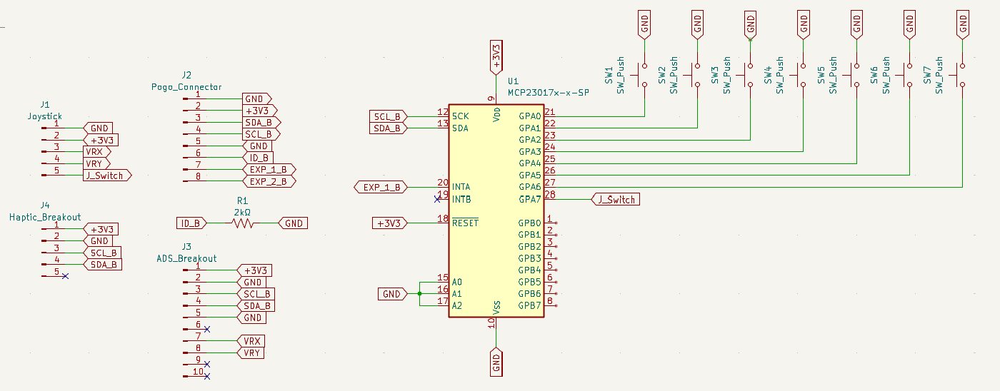
To determine which module is attached, each module has a resistor on the ID line that makes a voltage divider with a 1 kΩ resistor on the base. When you connect or disconnect a module, an interrupt fires and the Pico LiPo reads the voltage on that line. The gaming module reads about 2.2 V. Then it loads the right drivers. If you pull a module off in the middle of a game, it just goes back to the home screen. The user is only able to access programs associated with the connected module to prevent glitches and crashes.
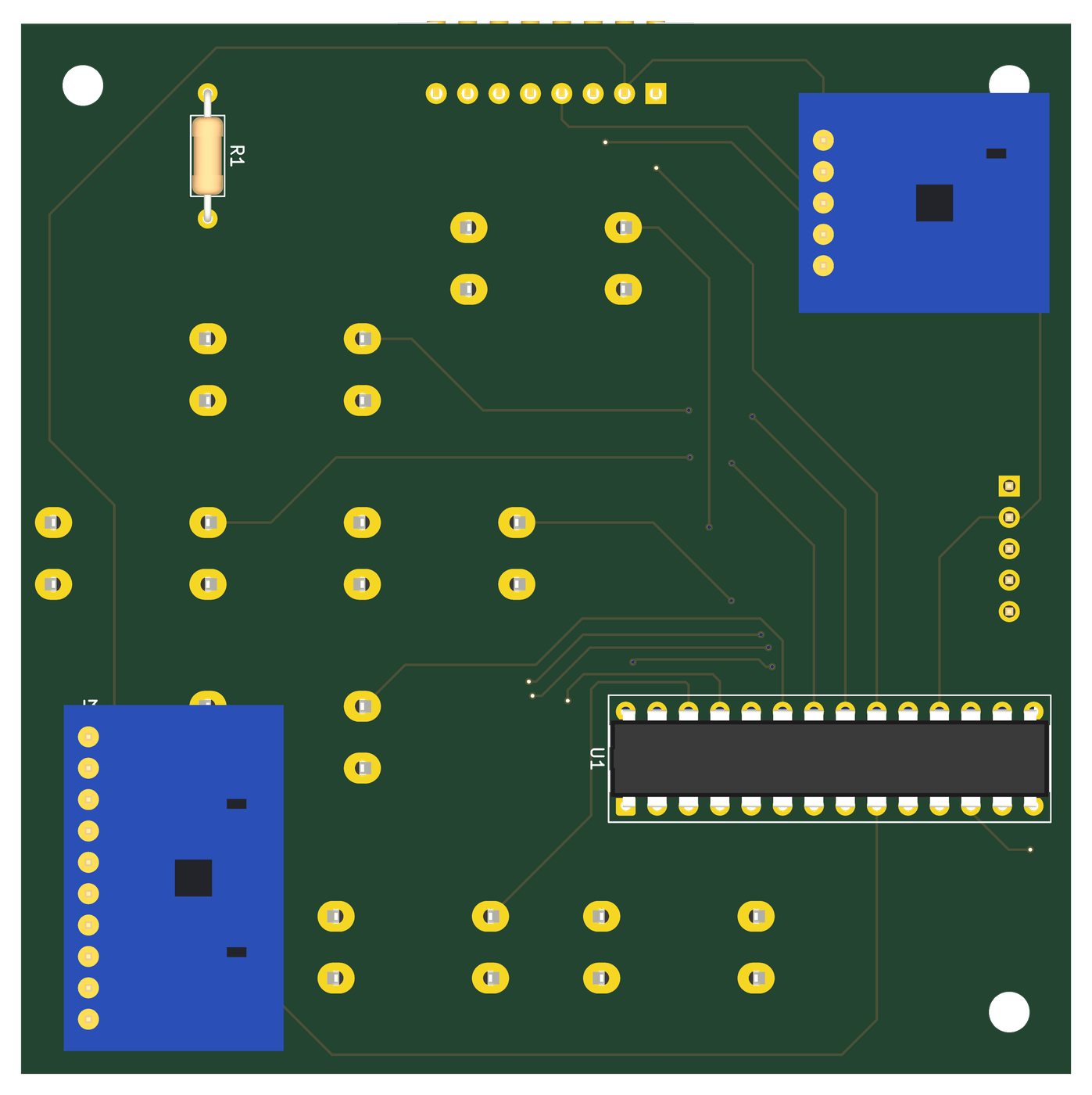
The gaming module has an MCP23017 I/O expander for the seven buttons and the joystick click, an ADS1115 ADC for the analog joystick, and a DRV2605 haptic driver. All three talk to the base over the same I2C bus.
Hardware Link to heading
Base unit Link to heading
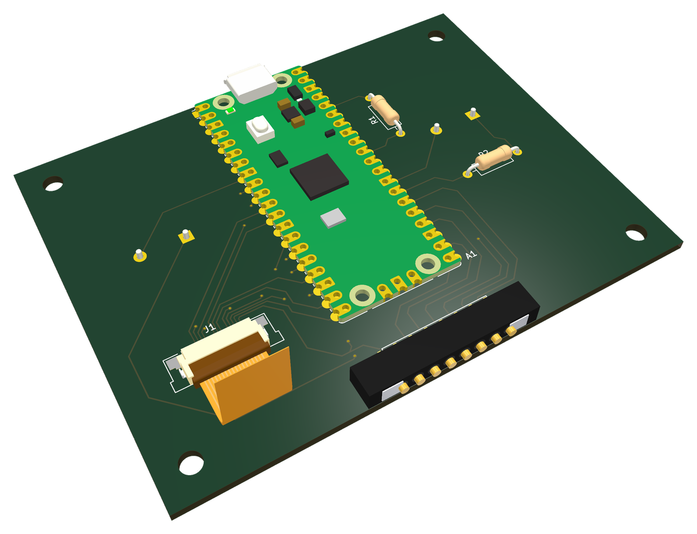
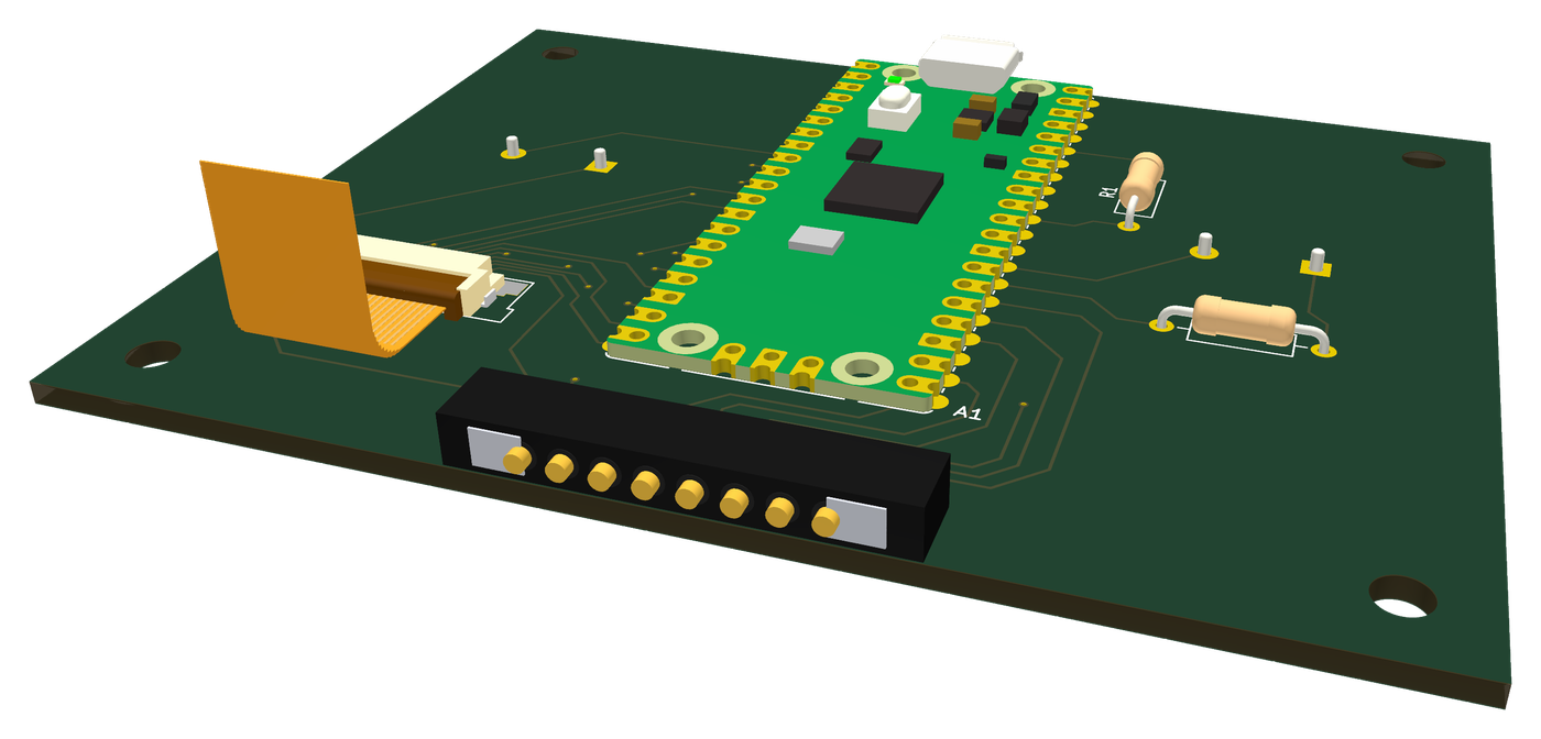
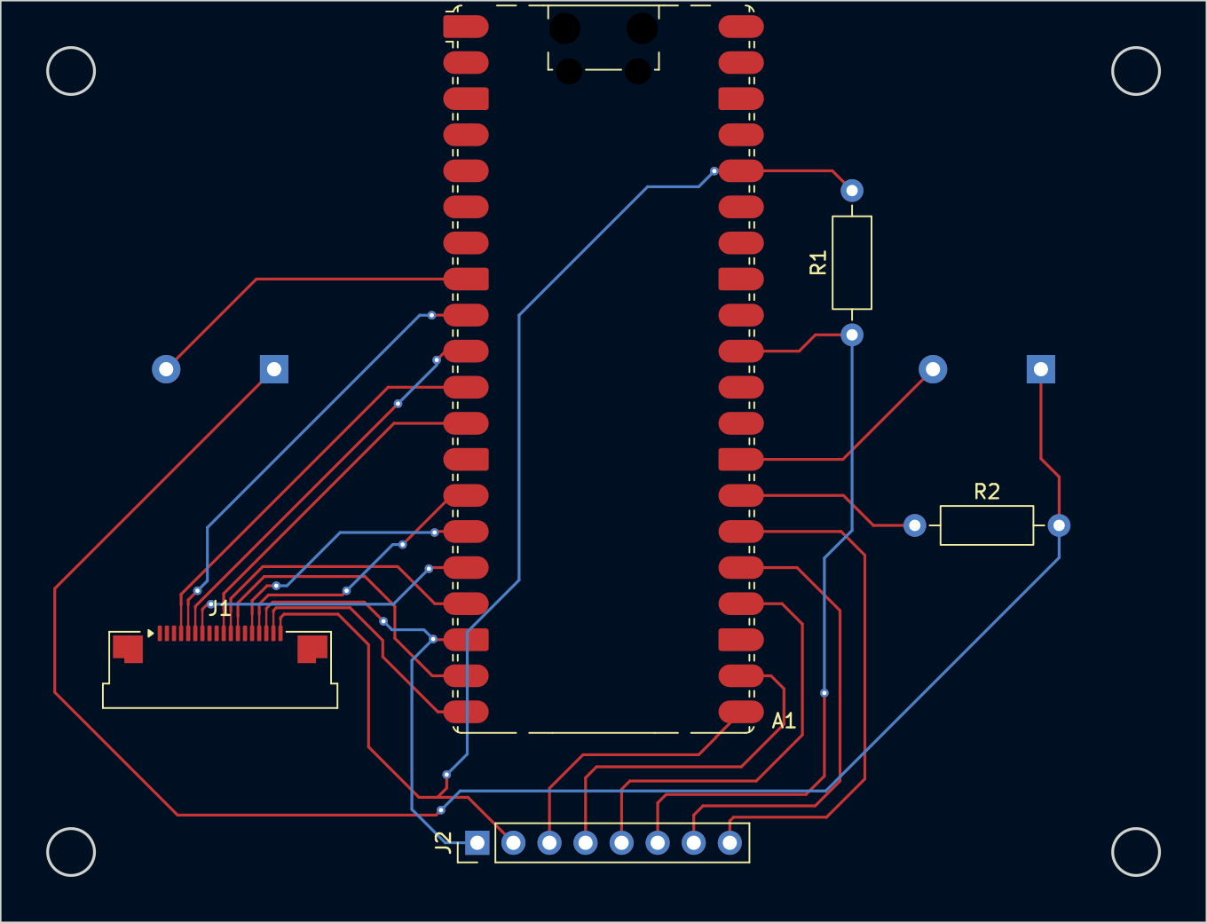
The base unit is a two-layer board I designed in KiCad. The Pico LiPo is in the middle, the display connector is on the left, and the pogo connector runs along the bottom edge where the modules attach.
Gaming module Link to heading
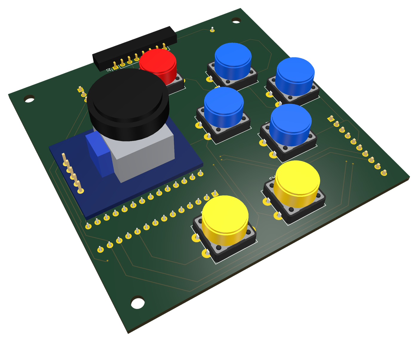
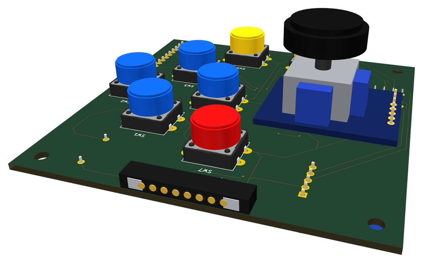
The gaming module is also a two-layer board designed in KiCad. The pogo connector runs along the top edge, the joystick is in the left middle, and the buttons fill the space left over. The MCP23017 and the ADS1115 are located on the back layer.
Software Link to heading
I wrote the software in MicroPython using the Thonny IDE. It has a home screen and game menu you control with the joystick and buttons and a settings menu for brightness, volume, and other miscellaneous features. There is also a battery indicator for percentage and charging status. Currently the only game is Tetris (with music and saved high scores), with plans for future 8-bit games such as brick breaker and space invaders.
What went wrong Link to heading
Electrical Link to heading
From an electrical standpoint, only one thing went wrong: the DRV2605 haptic driver. At one point in the project I had to unsolder then resolder the breakout board from the PCB, and I think the heat damaged the IC on the breakout. Everything else works as expected.
CAD Link to heading
The custom casing took many iterations to fine-tune the connection mechanism between modules due to my printer’s difficulty with the overhangs and circular shape of the twist lock. Currently, the pogo pins sometimes scrape the edge of the gaming module’s casing when twisting, which should be fixed in the next iteration.
Programming Link to heading
Programming was by far the most difficult part of this project. The first issue encountered was the locking up of the I2C line when disconnecting and reconnecting the gaming module since it tried to communicate over connections that no longer existed. To resolve this, I set it up so that when the interrupt is triggered, it also disconnects the I2C line then checks if the module is connected to reconnect the I2C line. This fixed the issue, although there is a bit of lag due to reinitializing the I2C line.
Throughout programming the home menu and gaming menu there were a couple of issues to fix but all of them were minor and have been resolved; the same goes for Tetris. The only current issue is with the battery detection code, which still has trouble detecting an interrupt for the charger getting connected/disconnected as well as a stable battery reading.
Future Plans Link to heading
My first goal is to clean up the code and optimize it for modularity and future expansion. I am considering switching to C instead of MicroPython, as it allows for more control over the device. The display does have touch screen capabilities which were not used during this iteration, but may be useful to implement.
I would also like to redesign the casing to prevent the pogo pins from scraping. Fixing the haptic feedback is also a priority.
Finally, I’m planning a music-creation module, a racing game module, and a keyboard module as future control systems to implement.